


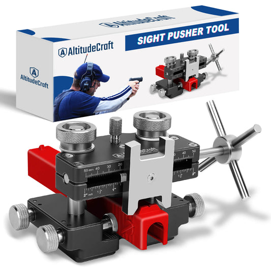

How to Remove and Replace Glock Sights: Direction, Tools, and What Actually Goes Wrong
Key Takeaway: A Glock rear sight sits in a through-cut dovetail, so it can exit either side of the slide — there is no factory-mandated direction. The convention most armorers follow is to drift it out to the left (left as you look at the pistol from behind, the same "left" used for windage). The front sight is a completely different job: it is held by a recessed hex nut under the slide that needs a thin-wall 3/16" driver, and neither Glock nor the major sight makers publish a torque figure for it — the documented instruction is finger tight plus blue threadlocker. Across 371 returns of our own sight pushers (261 with written comments), the two failures that actually stop people are not "the sight won't move" — they are the tool doesn't fit that pistol (20%) and the slide won't stay square in the clamp (10%). Both are preventable before you ever turn the screw.
Which Direction Does a Glock Rear Sight Come Out?
Drift a Glock rear sight out to the left. NRA's staff armorer states the direction plainly — "Twist the t-handle to drift the rear sight to the left until it is out of the dovetail." Note that the source says "left" without naming a viewing end; we read that as the shooter's left, the same "left" used in windage talk, which is the convention throughout this article. The dovetail is cut all the way through the slide, so the sight can physically exit either side. Direction here is a convention, not a mechanical rule.
That distinction matters, because the most common bad advice online is stated as if it were a factory spec. Here is what is actually established and what is not:
| Claim you will see online | Status |
|---|---|
| "Glock dovetails are tapered, so there is only one correct direction" | Not established. Glock does not publish a taper spec, and gunsmiths report both symmetric and slightly tighter-on-one-side dovetails across generations and production runs. |
| "Always drift left to right" / "always right to left" | Conventions, stated without a reference frame. Half the guides that say "left" mean left as viewed from the muzzle, which is the opposite of left as viewed from behind. Ignore any instruction that does not say which end you are looking from. |
| "Drift it out to the left, viewed from the rear" | Documented convention — this is the direction described by NRA's armorer walkthrough of a Glock sight swap. |
The practical rule that actually keeps you out of trouble: pick the conventional direction, apply firm and steady pressure, and if the sight has not started to move after the screw is genuinely loaded, stop and try the other side rather than adding force. A sight that will not move in one direction very often walks right out the other. Adding force is how dovetails get gouged and slides get bent in the clamp.

What 371 of Our Own Returns Say Actually Goes Wrong
We sell sight pushers, so the honest thing to do is tell you where ours fail. We pulled every return on our two sight pusher SKUs from July 2024 through June 2026 — 371 returns, 261 of them with a written customer comment — and classified the comments. The result is not what most installation guides warn you about:
| What actually went wrong | Share of 261 written comments | Can a guide prevent it? |
|---|---|---|
| Tool does not fit that pistol | 20% (51) | Yes — check fitment first |
| Slide will not stay square in the clamp | 10% (27) | Yes — seat and verify before loading the screw |
| Build quality: stuck or bent knob, missing front sight tools | 7% (19) | No — this is on us |
| Marred slide or sight | 3% (7) | Partly — over-clamping is avoidable |
| Not enough force / sight too tight | 3% (7) | Partly — oil and direction help |
| Front sight problems (driver too wide, nut stripped) | 2% (6) | Yes — it is a different job, see below |
| Red dot or adapter plate in the way | 2% (5) | Yes — remove the optic first |
Notice what is not at the top: cracked tritium vials, over-travel, finish damage — the failures every tutorial leads with. The real blockers happen before the sight moves at all. Two customer comments capture the pattern exactly:
"Does not work. As soon as pressure is applied to the sight. Unable to keep the slide square."
"Junk. Doesn't hold slide securely and flexes the slide within the unit."
Both of these got filed as "defective tool." Mechanically, they describe the same thing: the slide was never constrained, so the moment the pusher loaded up, the slide lifted or rotated and the pusher block skidded off the sight. That is fixable in thirty seconds — which is why Step 4 below exists and is missing from almost every other guide.
Will a Sight Pusher Fit Your Pistol?
If you are here for a Glock, you can skip this section — Glock slides are flat-sided and rectangular in section, which is the easiest possible case for a clamp-style pusher. If you are holding something else, read on, because of the "doesn't fit" comments that named a specific pistol, nearly every one named something other than a Glock:
| Pistol named in return comments | Count | Why it fights a clamp-style pusher |
|---|---|---|
| 1911 variants | 7 (most named) | Rounded, oval slide section. Flat clamp jaws cannot get a non-slip grip on a curved face, and the pusher block often cannot reach over the radius to the sight. |
| S&W M&P / Shield | 3 | Many aftermarket rear sights carry a set screw that must come out first (see Step 3). |
| Springfield XD / XD-M | 3 | Slide profile and dovetail height vary by generation. |
| Hellcat Pro, SIG P226, FN 509, HK VP9SK, Beretta M9, S&W Bodyguard 2.0 | 1 each | Micro-compact and wide-frame slides sit outside the jaw range. |
One customer put the 1911 case better than we could:
"A 1911 is oval. Does not hold a 1911 slide well enough and does not reach the sights over that rounded frame. It simply does not work."
Disclosure, because it is our own listing: our product pages have used the word "universal," and another customer answered that directly — "it clams to be universal but it is not." That is a fair hit. A clamp-style pusher is universal across flat-sided striker-fired slides. It is not universal across rounded 1911-pattern slides, and no amount of clamping force changes that geometry. Check your slide's cross-section before you order, not after.
Before you order: check the jaw width against your slide
There is a second fitment trap that has nothing to do with slide shape, and it is the one we caused ourselves. We have sold two different sight pushers under similar names, and they are not the same tool — different jaw capacity, different weight, different build. Older guides (including earlier versions of this page) illustrated one and linked the other. The specs below are read straight off each product's own spec sheet:
| Spec | Universal Sight Pusher Tool (the one linked below, in stock) | Sight Pusher Tool for Glock (older red unit, currently out of stock) |
|---|---|---|
| Max jaw width | 1.45 in / 36 mm | 1.22 in / 31 mm |
| Weight | 4 lb (bench-weight, meant to sit still) | 1.1 lb (hand-held clamp) |
| Material | Aircraft aluminium + steel | 6061 aluminium |
| Scales | Dual mm + inch, both sides | None |
Why the 36 mm number matters: a standard-width Glock slide sits well inside either tool's range, so most readers here never hit the limit. A wide-frame or competition slide can run past 31 mm, which would put it outside the older unit's jaw on spec alone. We are not claiming that is what drove any particular return — the named complaints in our data were about 1911 slide shape, not width — but it is a hard limit worth checking against your own slide. Measure the widest point of your slide, including any thumb ledge or optic plate overhang, before you order. If it is over 36 mm, neither of these is your tool.
Tools and Materials
- AltitudeCraft Universal Sight Pusher Tool ($85.99) — flat-jaw clamp with dual mm/inch scales, T-handle drive, and front sight tools included
- New front and/or rear sights (Trijicon HD XR, AmeriGlo, TruGlo TFX, XS Sights DXT2, Night Fision, or similar)
- Thin-wall 3/16" hex nut driver for the front sight nut — the standard size confirmed by Glock-specific front sight tools sold for this job
- Blue (medium-strength) threadlocker such as Loctite 242 for the front sight nut
- Hex key set — for set screws on aftermarket rear sights
- Clean microfiber cloth; light machine oil or CLP for the dovetail
- Safety glasses

How to Remove and Replace Glock Sights: 9 Steps
This is the complete sequence, from safety check to function check. Steps 3 and 4 are the two most commonly skipped, and they are the two that account for most of the failures in our return data.
Step 1: Clear the Weapon Completely
- Remove the magazine and set it aside, away from your work area
- Lock the slide to the rear using the slide stop lever
- Visually and physically inspect the chamber — look and feel to confirm it is empty
- Triple-check: magazine out, slide locked back, chamber empty
- Keep the muzzle pointed in a safe direction throughout
As the NRA Gun Safety Rules put it, treat every firearm as loaded until you have personally verified otherwise.
Step 2: Field Strip — Remove the Slide from the Frame
- Release the slide stop and let the slide run forward
- Pull the trigger to release the striker (the pistol is confirmed empty)
- Draw the slide back roughly 1/4 inch while pulling down both sides of the takedown lever
- Push the slide forward off the frame; set the frame aside
- Remove the recoil spring assembly and barrel so the slide sits flat
Step 3: Check for a Set Screw Before You Push Anything
Glock's own factory rear sights are polymer and friction-fit — no set screw. Many aftermarket rear sights are not. XS Sights states it plainly in their own installation guidance: "If your new or old Glock rear sight is secured by screws, you'll need an Allen bit to tighten/loosen them." The same is true across other platforms — one of our customers spelled out how much this matters:
"The sight pusher will not remove the rear sight of my M&P Shield 2.0. YES, the set screw was removed BEFORE using the removal tool."
Before the slide goes anywhere near the tool, look at the rear sight from the back and from underneath. If you see a small hex socket in the sight body or a threaded hole in the dovetail floor, back that screw fully out. Pushing against a live set screw will not remove the sight; it will bend the sight, gall the dovetail, or convince you the tool is broken. See our stuck and crooked sight troubleshooting guide if the sight still will not budge after the screw is out.
Step 4: Seat the Slide Square — Then Verify It
This is the step missing from nearly every tutorial, and it is the one that maps to 10% of our return comments. Do not tighten and go:
- Set the slide fully down into the jaws so it bottoms out — no gap under the slide
- Snug both clamp screws alternately, a little at a time, so the slide is pulled straight down rather than tipped to one side
- Verify before loading the pusher: the top of the slide should be parallel to the tool body, and the slide should not rock when you press a corner with your thumb
- Bring the pusher block into contact with the sight and confirm it meets the sight face flat and square — not on a corner, not riding up over the top edge
- Snug, not cranked. Over-clamping leaves witness marks on the finish and can flex a thin slide, which makes the dovetail grip tighter, not looser
If the slide rocks or the pusher block sits at an angle, back everything off and re-seat. Thirty seconds here saves a gouged dovetail.

Step 5: Drift the Rear Sight Out
- Note the starting reading on the tool's scale — this is your reference for centring the replacement
- Turn the drive screw slowly and steadily in the conventional direction (drifting the sight out to the left, viewed from the rear)
- The sight should start to creep. If it does, keep going until it clears the dovetail
- If it does not move once the screw is clearly loaded: stop. Add a drop of penetrating oil at both sides of the dovetail, wait ten minutes, and try again
- Still stuck? Re-seat the slide and push from the other side before you add force. The dovetail is a through-cut; the other direction is a legitimate option, not a last resort
Expect the factory polymer rear sight to show deformation where the block pressed on it. Plan on replacing it rather than reusing it.
Step 6: Remove the Front Sight (a Completely Different Job)
The front sight is not in a dovetail and a sight pusher cannot touch it. It is a post that passes through the slide and is retained by a hex nut threaded on from underneath — in NRA's words, "the front sight is affixed via hex screw accessible by the underside of the slide."
- Turn the slide upside down to expose the nut inside the slide channel
- Engage it with a thin-wall 3/16" hex nut driver; a socket with normal wall thickness will not fit down the channel
- Back the nut out counterclockwise and remove it completely
- Lift the front sight post straight up and out of the top of the slide
Six of our return comments were front-sight complaints, several of them variations on the driver being too fat for the channel or the nut stripping. Both come back to using the right size and getting the driver fully seated before applying torque.

Step 7: Install the New Front Sight
- Drop the new front sight post into the channel from the top of the slide
- Put one small drop of blue (medium-strength) threadlocker on the nut threads
- Start the nut by hand from underneath, then bring it home with the 3/16" driver
- Wipe away squeeze-out with the microfiber cloth
- Let the threadlocker cure before live fire — follow the cure time on the bottle
On torque: you will find "12 to 15 inch-pounds" and similar figures repeated across the internet, including in an earlier version of this article. We went looking for the source and could not find one. Neither Glock nor the sight manufacturers we checked publish a consumer torque spec for the front sight nut. What is documented is NRA's armorer instruction: "Dab a little blue (medium strength) Loctite on the threads" and "simply screw into the front sight until it is finger tight." XS Sights' own guide likewise gives no torque number. Snug plus blue threadlocker is the documented answer; a number with no source behind it is worse than no number.
Use blue, never red. Red threadlocker needs heat to break, which turns your next sight change into a project.
Step 8: Press In and Centre the New Rear Sight
- Wipe the dovetail clean, then wipe on a very thin film of light oil
- Start the new sight at the dovetail entrance and re-seat the slide in the tool using the Step 4 checks
- Drive it in slowly, checking every few turns
- Use the scale: bring the sight back to the reading you noted in Step 5, and it lands where the factory sight sat
- Confirm visually from directly behind — the notch should look centred on the slide
If you later need to correct windage on the range, the rule from XS Sights is the one to remember: move the rear sight in the same direction you want the point of impact to move. Want hits further right, move the rear sight right.
Step 9: Function Check and Reassemble
- Inspect both sights — flush, firm, no wobble, no new tool marks
- Reinstall barrel and recoil spring assembly, then the slide onto the frame
- Rack the slide, verify trigger reset, and confirm the slide locks back on an empty magazine
- Check the sight picture against a reference point before you go anywhere near live ammunition

What If There Is a Red Dot or Adapter Plate on the Slide?
Take it off first. Five of our return comments were people trying to push a sight with an optic still mounted, and the physics is unforgiving — the plate occupies the space the pusher block needs:
"Trying to remove a dovetail plate that a red dot attaches to. Plate is too big to fit in the sight pusher."
"Pusher mars sight and doesnt work with red dots attached to gun"
On an MOS-pattern slide, remove the optic and the adapter plate before the slide goes in the tool, then reinstall them after the sights are set. If you are running a dovetail-mounted optic — an optic that replaces the rear sight entirely — there is no rear sight to push; you are removing a plate, which is a different operation with different clearance requirements. Our Glock 43X MOS adapter plate comparison covers the plate side of that job.
Can You Remove Glock Sights Without a Tool?
Partly, and the honest answer splits by which sight you mean.
Rear sight — technically yes, but you are taking a real risk. A brass punch and a supported slide will drift a rear sight. What you lose is control: a punch delivers impulse, not measured travel, so there is no way to stop halfway and check. NRA's armorer is blunt about it: "Don't go banging away on it with your non-marring brass punch! I know it may seem like a good idea…but it isn't." If you go this route anyway, support the slide in a padded vise, strike the punch — never the sight body — and accept that overshooting is the normal outcome, not the exception.
Front sight — no. The retaining nut is recessed in a channel inside the slide. Pliers cannot reach it, a standard socket is too thick-walled to enter, and a screwdriver has nothing to grip. A thin-wall 3/16" driver is not a convenience here, it is the only access. This is the one part of the job with no workaround.
Night Sight Installation Tips
Tritium inserts are glass vials, and impact is what breaks them. When installing night sights like Trijicon HD XR or Night Fision units, keep the drive screw turning at a slow, consistent rate — jerky movement generates the same shock loading you were trying to avoid by not using a hammer.
Also verify sight height before you buy. Suppressor-height sights, sold for co-witnessing with a red dot, sit taller and will change your point of impact relative to standard-height replacements. Our Glock night sight upgrade guide and the full night sight installation walkthrough go deeper on selection.
Common Mistakes
- Loading the screw before checking the slide is square. The single biggest cause of "this tool is defective" in our own return data.
- Pushing against a set screw. Costs you a bent sight and a scarred dovetail. Check first (Step 3).
- Over-tightening the clamp. Snug, not cranked. Excess clamp force marks the finish and can flex a slide.
- Turning fast. Momentum overshoots centre. Small turns, frequent checks.
- Adding force instead of changing direction. If it will not move one way after oiling, try the other side.
- Red threadlocker on the front sight nut. Blue only.
- Assuming a pusher moves the front sight. It does not. Different retention system, different tool.
- Skipping the function check. Always reassemble and verify before the range.
For factory model specifications, refer to the official Glock website.

Sight Pusher vs. Hammer and Punch
The difference is not strength, it is measured travel. A punch delivers an impulse you cannot meter; a screw-driven pusher converts turns into a distance you can read off a scale, stop at, and reverse. That is what makes centring repeatable and what makes an overshoot recoverable instead of permanent.
The failure cases in our return data reinforce it from the other direction: almost none of them are "the screw could not generate enough force." They are fitment and setup — problems you diagnose before the sight moves, which is exactly the window a hammer does not give you. If you want a head-to-head on specific tools, see our AltitudeCraft vs Wheeler comparison and our 2026 sight pusher roundup.
Frequently Asked Questions
Which direction does a Glock rear sight come out?
Drift it out to the left, viewed from behind the pistol — the direction described in NRA's armorer walkthrough. The dovetail is cut through the slide, so it can exit either side; direction is convention, not a factory requirement. If it will not move one way after oiling and firm steady pressure, re-seat the slide and push from the other side rather than adding force.
Do Glock rear sights have a set screw?
Factory Glock rear sights are polymer and friction-fit in the dovetail with no set screw. Many aftermarket rear sights do use one, and it must be fully backed out before you push. Check the sight body and the dovetail floor for a hex socket before the slide goes in the tool.
What torque does the Glock front sight nut need?
Neither Glock nor the major sight manufacturers publish a consumer torque figure for it. The documented instruction from NRA's armorer is blue medium-strength threadlocker plus tightening until finger tight. Numbers in the 12 to 15 inch-pound range circulate widely online without an identifiable source — treat them accordingly.
Can I change a Glock front sight without a tool?
No. The retaining nut sits recessed in a channel inside the slide, where a screwdriver has nothing to grip and a standard-wall socket will not fit. A thin-wall 3/16" hex nut driver is the only practical access. The rear sight is the one that can be drifted with a punch, at the cost of control.
Will a sight pusher work on my non-Glock pistol?
It depends on the slide's cross-section, not the brand. Flat-sided striker-fired slides clamp well. Rounded 1911-pattern slides are the recurring failure in our own return data — flat jaws cannot grip a curved face and the pusher often cannot reach the sight over the radius. Check your slide profile and width against the tool's jaw range before ordering.
Why does my slide keep slipping in the sight pusher?
Almost always because it was never seated square. The slide must bottom out in the jaws, both clamp screws must be snugged alternately so it is pulled straight down, and the slide should not rock under thumb pressure before you load the drive screw. This accounts for 10% of the written comments across 371 returns of our own tools.
Do I need to remove my red dot before pushing sights?
Yes. The optic and its adapter plate occupy the clearance the pusher block needs, and trying to work around them is a documented cause of marred sights. Remove the optic and plate, do the sight work, then reinstall.
How long does a Glock sight replacement take?
Budget 30 to 45 minutes your first time, including clearing, field stripping, both sights, centring and reassembly. Once the seating routine is habit, 15 to 20 minutes is realistic. Most of the elapsed time is checks, not pushing.
Do I need threadlocker on the rear sight?
No. The rear sight is retained by the interference fit of the dovetail. Threadlocker belongs on the front sight nut only, which is a threaded fastener that can back off under recoil — and it should be blue, never red or green.
Related Articles
- How to Install Glock Night Sights with a Sight Pusher Tool — night sight selection, installation and zeroing
- Best Sight Pusher Tools for Glock 2026 — head-to-head tool comparison
- Glock Sight Pusher FAQ: Compatibility, Rear vs Front, and Tips
- Glock Sights Stuck or Crooked? Troubleshooting Guide
- AltitudeCraft vs Wheeler Sight Pusher: Honest Comparison
- Best Glock 43X MOS Adapter Plates
- Best Night Sight Upgrades for Glock
Disclosure: AltitudeCraft manufactures the sight pusher tools referenced in this article, and the return data cited here is our own. Product links lead to our own store. Follow all applicable firearms laws in your jurisdiction, and consult a qualified gunsmith if you are not comfortable performing sight work yourself.
📖 Part of our Sight Pusher Tool Complete Guide — tool selection, installation, troubleshooting and sight upgrades.
Last updated: August 2026
Related Articles
 Table Saw Alignment: How to Check Blade-to-Slot Parallelism (and When Your Saw Can't Be Fixed)
Sep 18, 2026
Table Saw Alignment: How to Check Blade-to-Slot Parallelism (and When Your Saw Can't Be Fixed)
Sep 18, 2026
 Weed Eater Harness Fit Guide: The 4 Adjustments That Decide Whether It Fits You (2026)
Sep 02, 2026
Weed Eater Harness Fit Guide: The 4 Adjustments That Decide Whether It Fits You (2026)
Sep 02, 2026
 Bullet Comparator Insert Chart: Which Insert Fits Your Cartridge (2026)
Aug 31, 2026
Bullet Comparator Insert Chart: Which Insert Fits Your Cartridge (2026)
Aug 31, 2026
 Framing Jig: Why Every One Has Play, and When It Beats a Tape (2026)
Aug 16, 2026
Framing Jig: Why Every One Has Play, and When It Beats a Tape (2026)
Aug 16, 2026
